BY NYC Energy Code Team
ON
13 October 2026
Solar Panel Weight and Roof Load: What Structural Engineers Check
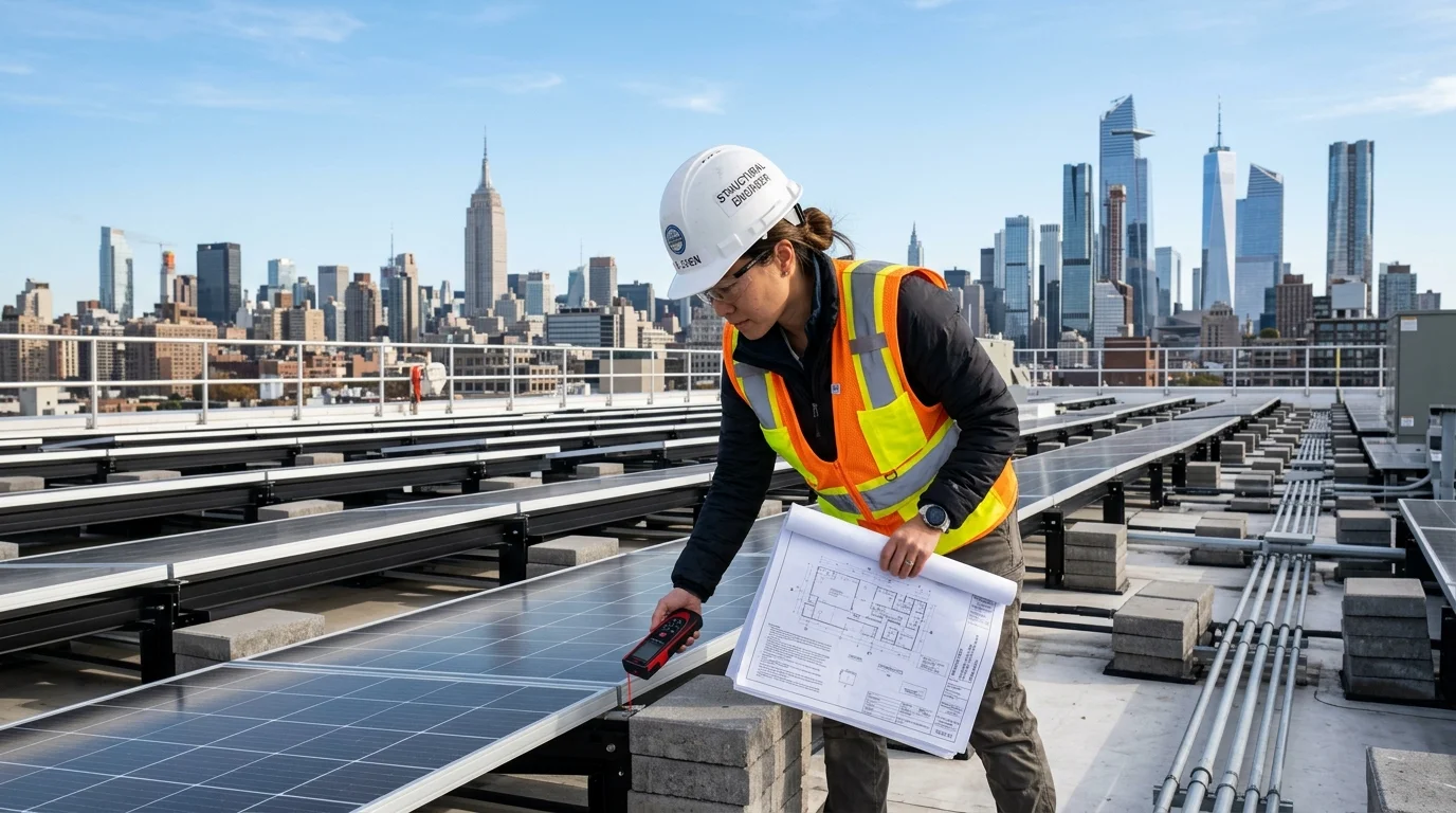
A flat roof can look like the perfect location for a solar installation. It provides open space, access to sunlight, and an opportunity to lower a building's electricity costs. Before panels are installed, however, one question needs to be answered: can the existing structure safely support the complete solar system?
The challenge is not limited to the weight of the panels. Mounting rails, support frames, ballast blocks, electrical equipment, and service walkways all contribute to the overall load. Wind can create uplift forces, snow may accumulate around the array, and poorly planned equipment placement can interfere with drainage.
These issues are particularly important for older New York City multifamily and commercial buildings, where the original structural design may predate rooftop solar installations.
A structural engineer evaluates how the complete solar system transfers its loads into the existing building—not simply whether the roof can support the weight of a few panels.
Understanding what goes into that assessment helps building owners identify structural constraints early, compare mounting options, and avoid expensive design changes after equipment has been purchased.
Beyond Module Weight
Evaluating rooftop solar structural capacity is never as simple as dividing panel weight by roof area. A complete structural analysis evaluates localized point loads, framing deck capacity, wind uplift aerodynamics, snow drift accumulation under NYC Building Code §1607, deflection, and ponding risks.
How Much Weight Do Solar Panels Add to a Roof?
Solar module weight varies by size, power rating, construction, and manufacturer. For example, Canadian Solar lists some modules weighing approximately 49.8 pounds and another 400-watt-class model weighing 56.7 pounds. These examples illustrate why engineers need the specifications for the actual product selected rather than a generic weight estimate.
Sources: Canadian Solar module specifications and Canadian Solar BiKu module datasheet.
The modules are only one part of the installation.
| Component | Structural Consideration |
|---|---|
| Solar modules | Their combined weight contributes to the permanent dead load |
| Mounting rails and frames | Transfer loads to supports and attachment points |
| Ballast blocks or pavers | Can substantially increase the weight of a non-penetrating system |
| Inverters and electrical equipment | May create additional loads at particular locations |
| Walkways and service platforms | Add weight and occupy roof space |
| Conduits and accessories | Contribute additional weight and may affect routing or support details |
The total installed weight can be significantly different from the combined weight stated on the module datasheets. A structural assessment must account for the entire proposed arrangement.
What Does Roof Load Capacity Actually Mean?
Roof load capacity refers to the ability of a roof and its supporting structure to resist the loads imposed on it under the applicable design conditions.
Engineers commonly consider both the total load and how that load is distributed.
Total load is the combined weight or force applied to the structure, measured in pounds or another appropriate unit.
Load per square foot, commonly expressed in pounds per square foot (psf), describes the load distributed across a defined area.
For example, suppose a solar system weighs 9,500 pounds and occupies a 2,500-square-foot footprint.
Average added load = 9,500 lb ÷ 2,500 ft² = 3.8 psf
The average added load is 3.8 psf. However, that number does not prove the roof can support the installation.
The weight may be concentrated at mounting feet, support rails, anchors, or ballast locations. Those points can experience higher local forces than the array's average load suggests. The roof deck, joists, beams, columns, connections, and other supporting elements must be checked as appropriate.
An apparently low average load can still create a structural problem if the system places concentrated forces on a weak or unsuitable part of the roof.
The Seven Structural Checks Engineers Perform
1
1. Existing Roof Framing and Available Capacity
Before evaluating the new solar system, the engineer needs to understand the structure already supporting the building.
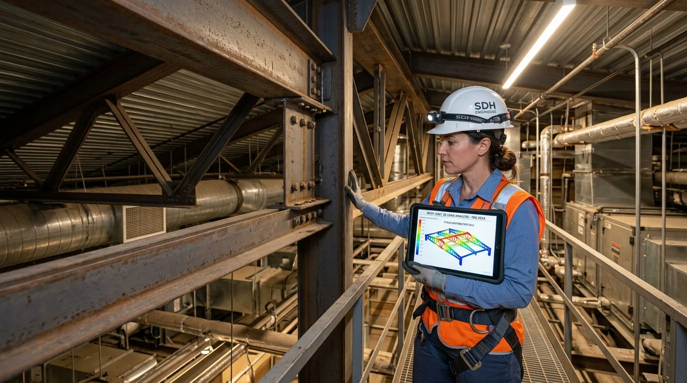
Depending on the property, this may include steel joists, beams, trusses, concrete slabs, roof decking, columns, load-bearing walls, and structural connections. Original drawings can help establish the framing layout and intended design loads, although the engineer may need to verify whether the drawings match current conditions.
Existing rooftop equipment is also relevant. HVAC units, water tanks, mechanical supports, and previous installations already contribute to the building's loads.
The assessment should account for structural deterioration and alterations where relevant. Corrosion, damaged connections, previous modifications, or water-related deterioration may affect the capacity available for new equipment. A roof that has supported its existing loads for decades is not automatically suitable for a solar array. The proposed installation must be evaluated against the applicable structural design requirements.
2
2. Total Dead Load From the Solar System
Dead load is the permanent weight of the building and its fixed components. For rooftop solar, the calculation includes the panels, mounting components, ballast where used, and other permanent equipment associated with the installation.
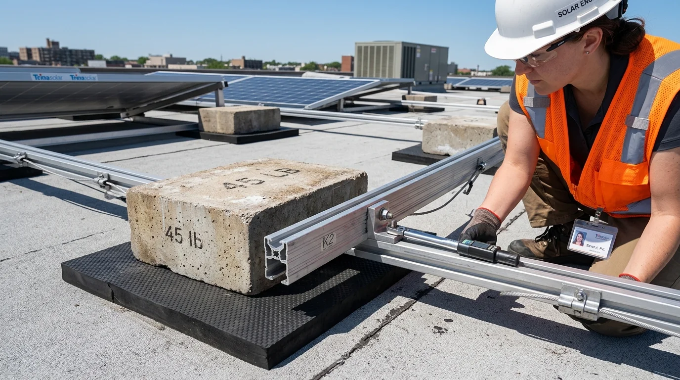
The mounting method can make a substantial difference. A mechanically attached array transfers loads through engineered attachments into the supporting structure. A ballasted system relies on added weight to resist wind forces without relying on the same type of roof penetrations.
Ballasted systems can reduce penetration-related waterproofing concerns, but the amount and location of ballast must be determined by the mounting design and applicable structural calculations. Additional ballast increases the load that the roof must support. The engineer therefore needs manufacturer information and a layout showing the proposed panels, support locations, attachments, and ballast distribution.
3
3. Concentrated Loads at Support Points
One of the most important checks concerns the points where the mounting system transfers loads to the roof.
Consider a solar array supported by a series of rails. The rails distribute the weight of the panels to individual mounting feet or attachments. If a support falls between suitable structural members, the roof deck may experience a local load that it was not designed to carry.
The structural engineer examines the relationship between the mounting layout and the existing framing. Depending on the system, the design may require different support locations, revised ballast distribution, engineered attachment details, or localized reinforcement. This is why calculating only the combined panel weight divided by the array's footprint is insufficient. The actual load path matters as much as the total load.
4
4. Wind Uplift and Sliding Forces
Solar panels alter the way wind interacts with a rooftop. Depending on the array's geometry and mounting arrangement, wind may create uplift, sliding forces, and other loads on the panels, support frames, attachments, and roof structure.
Relevant conditions can include roof height, wind exposure, nearby buildings, panel tilt, array location, and proximity to roof edges or corners. A ballasted system must provide sufficient resistance to the applicable wind forces. An attached system must transfer the corresponding forces through its connections and into the supporting structure.
Adding more ballast without a proper calculation is not an acceptable substitute for engineering analysis. Too little resistance can create a wind-safety risk, while excessive ballast can introduce unnecessary structural demand. The engineer evaluates the mounting system as a complete assembly and checks the appropriate load combinations under the applicable building code.
5
5. Snow Loads and Snow Drifting
Snow loading is another important consideration for rooftop photovoltaic systems. The panels can change how snow accumulates, slides, or drifts across the roof. Depending on the roof geometry and array configuration, snow may accumulate around panel rows, adjacent parapets, and nearby rooftop equipment.
The engineer determines the relevant snow loads and evaluates any additional or redistributed loads required by the design rules.
NYC Building Code Section 1607.13.5.2 states that roof structures supporting photovoltaic systems must accommodate the full panel and ballast dead load, including concentrated support-frame loads, in combination with applicable roof loads. Where applicable, snow-drift loads created by the panels must also be included. Source: NYC Building Code §1607.13.5.2. The objective is to evaluate the complete structural demand under the applicable conditions rather than checking the panel weight in isolation.
6
6. Deflection and Roof Ponding
A roof may have enough strength to avoid structural failure but still experience excessive movement. This movement, known as deflection, can affect mounting alignment, roofing components, and the roof's ability to drain water.
Ponding occurs when water accumulates on a roof. In certain conditions, roof deflection can allow water to collect, adding weight and potentially worsening the deflection. Solar mounting feet, ballast blocks, and equipment layouts can also interfere with drainage if the design is not coordinated carefully with roof slopes and drain locations.
NYC Building Code Section 1607.13.5.4 specifically requires roof structures supporting ballasted photovoltaic systems to be analyzed under the applicable structural provisions, checked for deflection, and checked for ponding. Source: NYC Building Code §1607.13.5.4. These checks help ensure that the system does not create unacceptable movement or interfere with the roof's intended drainage performance.
7
7. Roof Condition, Waterproofing, and Maintenance Access
Structural feasibility does not guarantee that an installation is practical for the roof itself.
The engineer and project team also need to account for the roof membrane, flashing, insulation, drainage outlets, and the locations of any required penetrations. Mechanically attached systems need appropriate penetration and waterproofing details. Ballasted systems must be compatible with the roofing assembly and must not obstruct drainage or create unacceptable localized pressure.
Roof age is also relevant. If replacement is approaching, coordinating the roof work with solar installation may reduce the future cost and disruption of removing and reinstalling the panels.
The planned array should preserve safe access for maintenance and required clearances around rooftop equipment. Structural planning works best when coordinated with the roofing contractor, solar designer, and electrical team from the start.
A Worked Example: Calculating the Added Solar Roof Load
Consider a hypothetical NYC office building planning to install 100 solar panels.
For this example, assume the following weights:
| Component | Assumed Weight |
|---|---|
| 100 solar panels at 50 lb each | 5,000 lb |
| Mounting hardware and support frames | 2,000 lb |
| Ballast blocks | 2,500 lb |
| Total assumed system weight | 9,500 lb |
Assume the complete array occupies a footprint of 2,500 square feet.
Average added load = 9,500 ÷ 2,500 = 3.8 psf
Under these illustrative assumptions, the system adds an average of 3.8 pounds per square foot over its footprint.
These are example values, not a standard system specification or a recommendation for ballast. Actual equipment weights and support layouts must come from the project's design documents and manufacturer data.
More importantly, 3.8 psf is not a roof-capacity rating. It does not establish whether the roof can carry the installation. The structural engineer must evaluate the load distribution, individual support reactions, existing framing, applicable wind and snow loads, roof live loads, deflection, ponding, and the relevant load combinations.
The calculation is useful for preliminary planning, but it cannot replace a project-specific structural analysis.
What NYC Requires Before Rooftop Solar Installation
The New York City Department of Buildings (DOB) states that property owners must hire a Professional Engineer (PE) or Registered Architect (RA) to assess whether the building's structure can support the added solar equipment weight. Building-connected solar installations require permits, and associated electrical work is subject to separate permitting requirements.
DOB also identifies structural analysis of the existing building as part of the construction-document process for applicable solar projects.
Sources: NYC DOB — Solar Panels and NYC DOB — Project Requirements for Solar Systems.
For an owner, the practical lesson is simple: arrange the structural review before finalizing equipment orders or assuming that a proposed array will fit the roof.
Depending on the findings, the design professional may determine that the roof can support the installation as proposed, that the array needs a revised layout or lighter mounting system, or that reinforcement must be investigated.
The project's filing, inspection, and sign-off requirements should be confirmed for its exact scope.
What Documents Should Building Owners Prepare?
A structural review is more efficient when the design team has reliable information about the building and the proposed system.
- Original structural drawings: Gather structural and architectural plans where available, including framing layouts, design dead and live loads, and member sizes.
- Records of previous roof alterations: Documentation of previous reroofing projects, structural repairs, or HVAC equipment additions.
- Rooftop mechanical equipment inventory: Locations and weights of existing HVAC units, water tanks, mechanical curbs, and dunnage supports.
- Preliminary solar array layout: Drawings showing panel locations in relation to framing lines, roof drains, parapets, roof edges, access walkways, and fire department clear paths.
- Manufacturer cut sheets and specification data: Detailed datasheets for the modules, mounting rails, supports, anchors, and ballast pavers showing exact component weights.
If the existing drawings are unavailable or differ from field conditions, the engineer may need additional site investigation or measurements to verify the structure. Providing these records early can reveal design constraints before permitting, procurement, or installation is underway.
Common Mistakes to Avoid
- Using panel weight as the total system weight: Mounting hardware, ballast, conduits, and other permanent equipment must also be considered.
- Relying on average pounds per square foot: Average load can conceal concentrated forces at support points and does not prove that a roof member has sufficient capacity.
- Choosing ballast by rule of thumb: Ballast requirements depend on the engineered mounting design and applicable wind forces. Adding weight without checking structural capacity can create a different problem.
- Ignoring drainage and the condition of the roof: Solar layouts must account for ponding, roof drains, waterproofing, and maintenance access.
- Waiting until installation is scheduled to request a structural assessment: Discovering that reinforcement or a revised mounting system is needed after equipment has been ordered can increase costs and cause delays.
Conclusion
Solar panel weight and roof load are closely connected, but determining whether a roof can support solar requires much more than adding up the weight of the modules.
Structural engineers evaluate the full system, its mounting and ballast, load concentrations, existing framing, wind uplift, snow loads, deflection, ponding, and roof conditions. These checks establish whether the proposed installation can be supported safely under the applicable design requirements.
For NYC building owners, the structural assessment also forms part of the city's rooftop solar approval process. Starting early helps identify constraints, compare mounting strategies, and coordinate structural work with roofing and electrical upgrades.
The most reliable first step is to assemble the structural drawings and equipment specifications, develop a preliminary array layout, and engage a qualified design professional to assess the actual building.
Frequently Asked Questions
It depends on the model. Manufacturer specifications for some modules in the examples cited above are approximately 49.8–56.7 pounds. The selected panel's actual data sheet should be used for calculations.
There is no universal figure. Total system load depends on module weight, mounting hardware, ballast, equipment, and system layout. An engineer must evaluate both the average load and the forces at individual supports.
A qualified structural engineer or registered design professional should evaluate the existing structure, proposed equipment, mounting details, and applicable design loads. Panel weight alone cannot establish roof capacity.
Not always, but ballasted systems can require substantial extra weight to resist wind forces. The appropriate mounting method depends on the roof, structural capacity, wind conditions, waterproofing requirements, and engineered system design.
Yes. The applicable requirements address environmental loads and how they interact with the solar system. NYC Building Code provisions specifically address panel and ballast dead loads, concentrated support loads, and applicable snow-drift effects.
NYC DOB requires a PE or RA to assess whether the existing building can support the added solar equipment weight and to prepare the required project documentation. The full permitting and inspection requirements depend on the installation's scope.
Potentially. Options may include revised support locations, a different mounting arrangement, reduced ballast, or engineered reinforcement. A structural engineer must determine what is feasible for the specific building.
Not necessarily. However, roof age, condition, and expected remaining service life should be considered. Coordinating roof replacement and solar installation may prevent the added expense of removing and reinstalling the array later.
You may also like